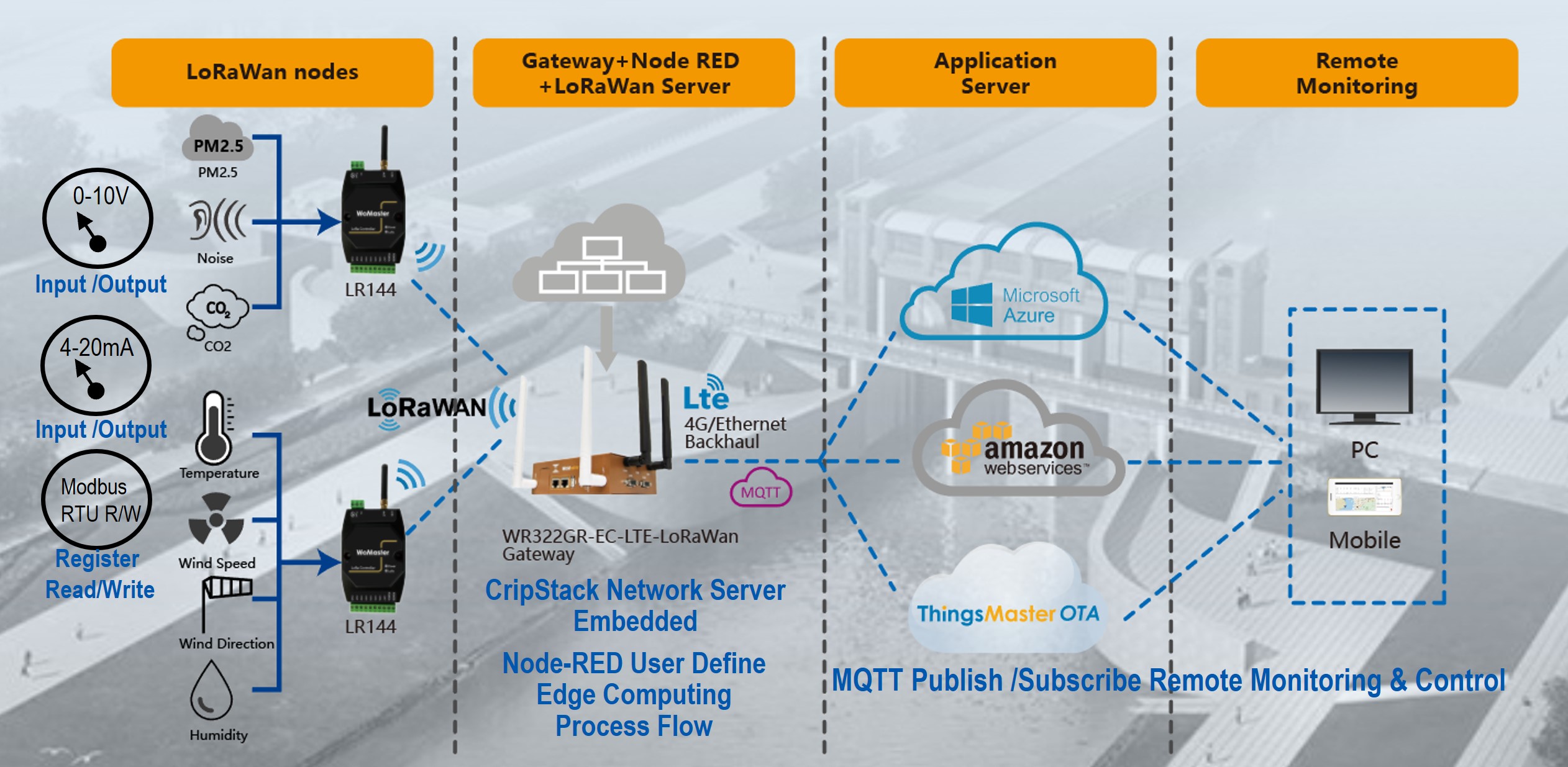
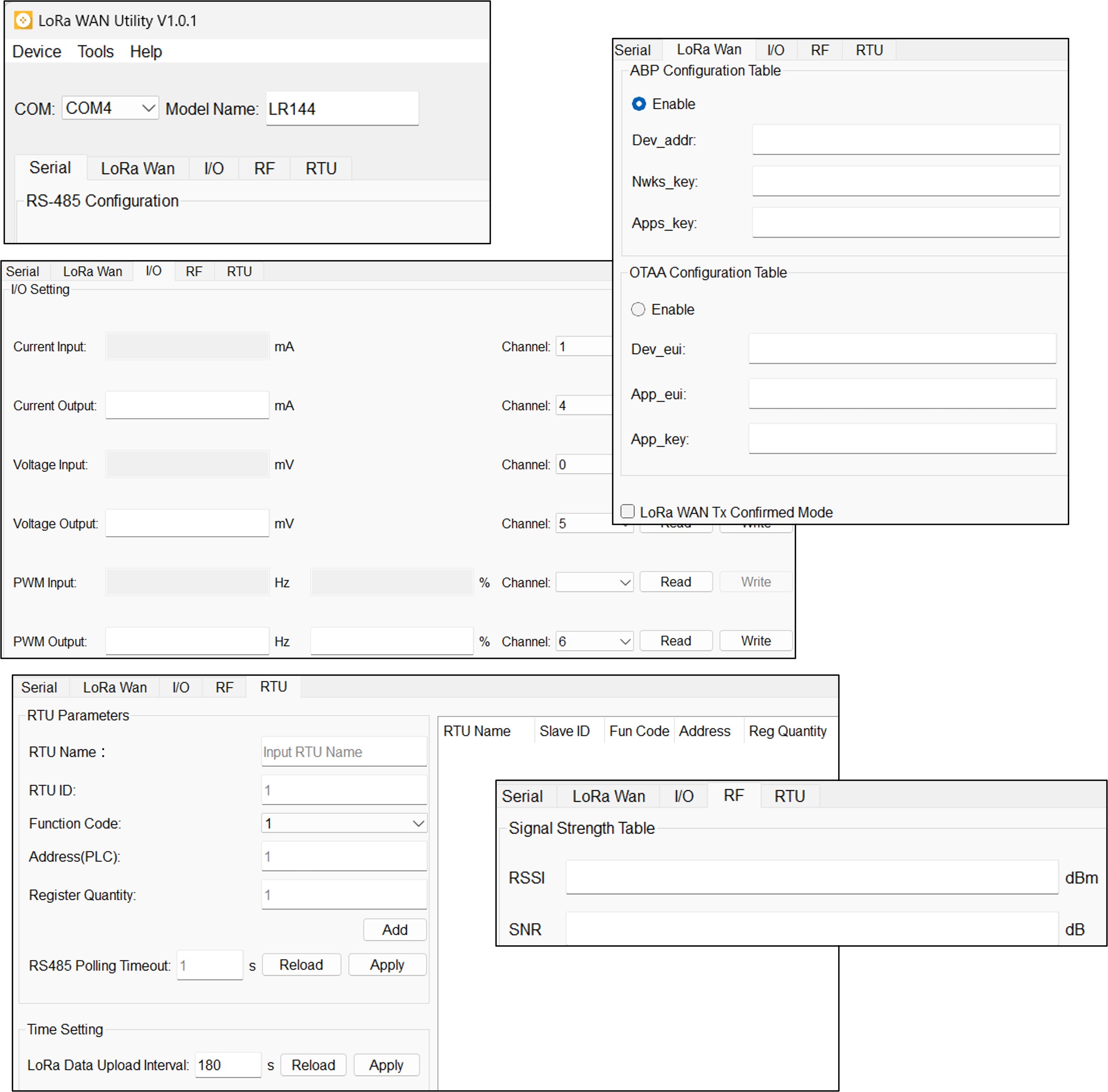
LR144

The LR144 series utilizes the latest Low Power Wide Area (LPWA) technology to build long-distance, wide-coverage, and low-power wireless IoT applications. Multiple analog inputs and outputs are supported in the LR144 series, such as 0-10V, 4-20mA current, 5V PWM, 0-10V PWM for traditional electromechanical control and sensing, and the RS-485 port supports Modbus Host mode for the filed site automation controller- PLC, DCS or any device with Modbus communication interface. Its regular Modbus register data pulling function ensure the control center gets the latest data. The LR144 series offers great flexibilities in wireless IoT applications, such as traditional analog sensors acquisition and Modbus/RTU devices remote control, integrated with LoRa WAN gateway that can achieved edge computing/control and enhanced your Industrial IoT process such WR322GR LoRaWAN series.
Related Downloads Inquiry cart

LoRa WAN End-Node Control

•LoRa WAN Class-C operating mode, Bi-directional end-devices with maximum receive time slots offers the ABP, OTAA Network Connection modes
•Lowest latency for server-to-end-device communication
•Supports Spreading Factor 5,6,7,8,9,10,11,12
 

Reliable Radio Communication

• LoRa WAN TX Confirmed Mode support
•Adjustable LoRa Data Upload Interval time
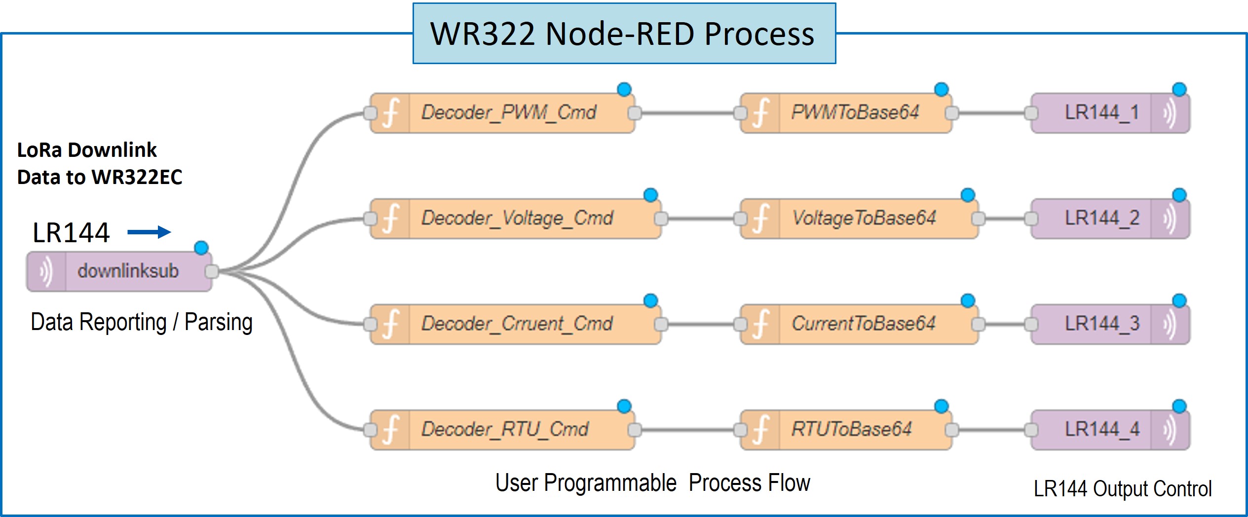
LoRa WAN to Modbus/RTU control

•Modbus RTU data Upload / Download with Gateway
•Remote Control with End-Node Acknowledge
•Maximum 20 RTU Entries, Scheduling polling
•Non-Limited RTU Entry for Downlink Control

RS485 Modbus Function Code

•Code 01: Read Coil-Read  Output Control bit
•Code 02: Read Discreet-Read  Input bit, Read Input bit
•Code 03: Read Holding Register – Read Output word
•Code 04: Read Input Registers – Read Input Word
•Code 05: Write Single Coils – Write one bit output
•Code 06: Write Single Coils – Write one word output
•Code 15: Write Multiple Coils – Write a number of output bits
•Code 16: Write Multiple Registers - Write a number of output words

Various RTU Data Format

•Integer, Unsigned Integer, Float, Short, Un-signed Short, ASC II

LoRa WAN Remote Control, Monitoring

•2 Channels 0~10V Input, High Impedance, Accuracy 2 ‰
•1 Channel 0~10V Output, Open Drain  Output, Accuracy 2‰
 
•2 Channels 4-20mA Current Sensing, 0.3%High Accuracy
•1 Channel 4-20mA Current Output, 3 ‰ High Accuracy
•1 Channel 5V PWM Output
•1 Channel 10V Open Drain PWM Output
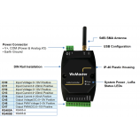
Windows© Configuration Utility

•User-Friendly, Auto Detection Model
•Radio Signal Check
•Analog IO Parameter Read and Write
•RTU Device Register Pulling Setting
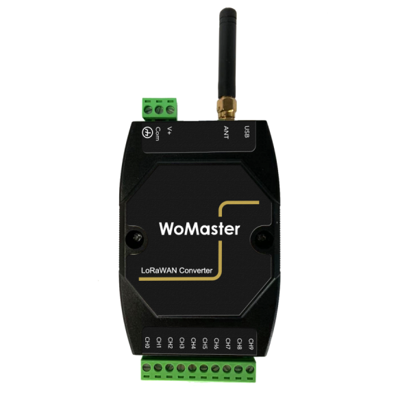
•Micro-USB Interface
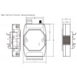
 

Industrial Application

•10~30V DC wide power range input
•Low Power Consumption
•Wide Coverage up to 6KM (Max)
•-40 ~ 75°C / 90%H  Operating Temperature / Humidity
•Compliance IEC 61000-6-2/-6-4 Heavy Industrial EMC

Wireless Specification
Frequency

LR144-EU433 (Region Code): 433~434Mhz

LR144-EU868 (Region Code): 863~870Mhz

LR144-US915 (Region Code): 902~928Mhz

LR144-AS923 (Region Code): 920~923.5Mhz, Group AS923-1

LR144-KR920 (Region Code): 920~923Mhz

LR144-CN470 (Region Code): 470~510MHz

Wireless Technology Low Power Wide Area – LoRa WAN Technology
Radio TX Power 22dBm
Radio RX Sensitivity - 148dBm, SF=12 @ 250bps
Spreading Factor

SF5/SF6/SF7/SF8/SF9/SF10/SF11/SF12, Default SF7; the Class-C RX2 Spreading Factor regarding the LoRa WAN standard 1.0.2 , please refers to User Manual.

Demodulator SNR LoRa Demodulator Signal to Noise Ratio: -2.5dB ~ -20dB
Operating Mode

System operating in LoRa WAN Class-C Mode, OTAA and ABP joint modes

Supports TX Confirmed function, configured through the LoRa WAN Utility

Adjustable Regular LoRa Data Uploading interval time – 5 minutes (Min.)

Forwarding Data Buffer 256Bytes FIFO Data Buffer for LoRa signal transmission
Data Encryption 128bits AES with configurable key
Management
System Management 1 x Micro USB 2.0 port for system configuration
Software Utility Windows© Based  Utility
I/O Interface
Antenna Connector 1x 50 ohm, Female SMA
Serial Interface 2-wires RS-485 Terminal Connector with 1kv isolation
Connector Type: Removable Terminal Connector

Supported Model: LR-144(Modbus Host)

Serial Parameters Baud Rate: 1200bps, 4800bps, 9600bps,115,200bps
Data Bits: 8
Parity Check: None
Stop Bit: 1
CRC: Enable (default)
Current I/O

4~20mA Input: 2 Channels

Accuracy Level: 0.3%

4~20mA Output: 1 Channel

Accuracy Level: 0.3%

Voltage I/O

0~10V Input: 2 Channels

Accuracy Level: 0.2%

0~10V Output (Open Drain): 1 Channel

Accuracy: 0.2%

5V PWM Output: 1 Channel

Voltage Accuracy: 0.2%

Adjustable Duty Cycle, 100Hz ~1KHz

10V PWM Output (Open Drain): 1 Channel

Voltage Accuracy: 0.2%

Adjustable Duty Cycle, 100Hz ~1KHz

Modbus RTU Function Code

Support RS-485 Modbus Host with Function Code:

Code 01: Read Coil - Read Output Control bit

Code 02: Read Discreet - Read Input bit

Code 03: Read Holding Register - Read Output word

Code 04: Read Input Registers - Read Input Word

Code 05: Write Single Coils – Write one bit output

Code 06: Write Single Coils – Write one word output

Code 15: Write Multiple Coils – Write a number of output bits

Code 16: Write Multiple Registers - Write a number of output words
System Indication  
LED Power (On):  System Power applied
LoRa (Blinking): LoRa RF Signal on Communication
Power Requirement
Input Rating Typical DC 24V, Rating: 10~30V
3-Pins Removable Terminal Connector for V+ ,Com and Earth Ground
Reverse Protection Yes
Power Consumption LR144: 3 Watts @ DC 24V power input
Mechanical
Installation DIN Rail Mount
Enclosure Material UL94v0, ABS , Anti- U/V
Ingress Protection IP 40
Dimension 26(D) x 102.5 (H) x 72 mm (W)  / with wall mounting clip
Weight 115g
Environmental
Operating Temperature -40°C~75°C, 0% ~ 90%, Non-Condensing
Storage Temperature -40°C~80°C, 0% ~ 90%, Non-Condensing
Reliability & Warranty
MTBF 20000> Hours
Warranty 3 Years, No-Natural damaged
Standards
EMC Compliance with IEC / EN61000-6-2, IEC/ EN61000-6-4
EMI Electromagnetic Immunity: CISPR 22, FCC part 15B Class A
EMS Electromagnetic Suspension:
IEC 61000-4-2 ESD
IEC 61000-4-3 RS
IEC 61000-4-4 EFT
IEC 61000-4-5 Surge
IEC 61000-4-6 CS
IEC 61000-4-8 Pulse Magnetic Field

LoRaWan Remote Control Application & Architecture 

WR322GR-EC-LTE-LoRaWAN gateway converts LoRaWAN™ data collected from LoRaWAN™ End nodes LR144 to MQTT and transmits to the cloud through the LTE network.
LR144 analog input output to LoRaWAN converter


LR144 with WR322 LoRaWAN gateway Node-RED Process Flow 

LR144 analog input output LoRawan node with WR322 lorawan gateway Node-RED Process Flow

LoRaWAN Utility 
lorawan utility

Model Description

LR144-EU433

LR144-EU868

LR144-AS923

LR144-KR920

LR144-US915

LR144-CN470

LR144-(Region Code), 2 CHs 4-20mA Input, 2 CHs 0-10V Input, 1CH 20mA Output, 1CH 10V Output, 1CH 5V PWM, 1CH10V O.D. PWM, 1 Modbus RTU 485 Host

1 x 2-Wire RS485

1 x SMA Connector

Packing & Accessories
LoRa Device x 1
6dBm SMA Antenna x 1
Quick Installation Guide x1
 
Optional Order  
MDR-40-24 Din Rail Power Supply, INPUT:85-264VAC, 120-370VDC, OUTPUT: 24VDC/1.7A, -20 ~ +70℃
ThingsMaster OTA-Annual Fee-100 ThingsMaster OTA Online OTA annual fee for 100 nodes
WR322GR-EC-LTE-LORAWAN-EU868
WR322GR-EC-LTE-LORAWAN-EU433
WR322GR-EC-LTE-LORAWAN-US915
WR322GR-EC-LTE-LORAWAN-AS923
WR322GR-EC-LTE-LORAWAN-CN470
Industrial LoRaWAN Gateway, 2GbE+2COM, LTE 2SIM, FDD B1/3/7/8/20/28A, LoRaWAN 868/433/915/923/470MHz